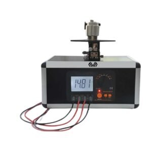
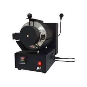
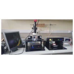
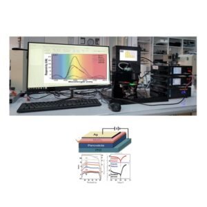
FOUR PROBE CHARACTERIZATION SYSTEM includes
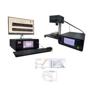
The system is a complete FOUR PROBE CHARACTERIZATION SYSTEM.
The system contains the following elements:
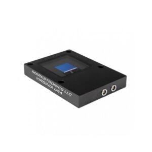
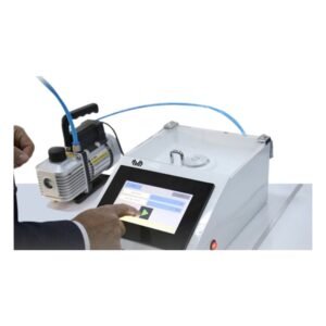
Probe station
Micropositioner
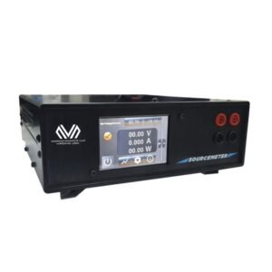
Sourcemeter:
Current range: 10 nA- 250 mA
What is a Four-Point Probe?
The four-point probe is the most commonly-used piece of equipment for measuring the sheet resistance of a material. Sheet resistance is the resistivity of a material divided by its thickness, and represents the lateral resistance through a thin square of conducting/semiconducting material. This measurement uses four probes arrayed in a line, with equal spacing between each probe. A current is passed between the outer two probes, causing a reduction in voltage between the inner two probes. By measuring this change in voltage, the sheet resistance can then be calculated.
Method of operation
• A four point probe is typically used to measure the sheet resistance of a thin layer or substrate in units of ohms per square by forcing current through two outer probes and reading the voltage across the two inner probes. Using this four-terminal configuration avoids measurement error due to the contact resistance between the probe and sample.
• The probes are collinear and are equally spaced.
• Probe spacing for the LNF tools is 1.59mm
• For film thickness ≤ 0.5 x (probe spacing) and diameter or lateral dimensions > 40 x (probe spacing), the sheet resistance calculation simplifies to:
•
Here, I is the applied current and ΔV is the decrease in voltage between the inner probes. The result of this equation must further be multiplied by a geometric correction factor based upon the shape, size, and thickness of the sample. This accounts for limitations to the possible current pathways through the sample, which affects the values that are measured.
A more in-depth explanation of the theory behind sheet resistance, geometric correction factors, and the four-point probe technique can be found in our Guide to Sheet Resistance Theory.
What is Sheet Resistance?
________________________________________
Sheet resistance (also known as surface resistance or surface resistivity) is a common electrical property used to characterise thin films of conducting and semiconducting materials. It is a measure of the lateral resistance through a thin square of material, i.e. the resistance between opposite sides of a square. The key advantage of sheet resistance over other resistance measurements is that it is independent of the size of the square – enabling an easy comparison between different samples.
This property can easily be measured using a four-point probe and is critical in the creation of high-efficiency perovskite photovoltaic devices, where low sheet resistance materials are needed to extract charge.
General Theory
The primary technique for measuring sheet resistance is the four-probe method (also known as the Kelvin technique), which is performed using a four-point probe. A four-point probe consists of four equally spaced, co-linear electrical probes, as shown in the schematic below.
A schematic diagram of a four-point probe. The four probes have equal spacing (s) and are shown in contact with a surface. A current (I) is injected through probe 1 and collected through probe 4, whilst the voltage is measured between probes 2 and 3.
It operates by applying a DC current (I) between the outer two probes and measuring the resultant voltage drop between the inner two probes.
The Sheet Resistance Equation
The sheet resistance can then be calculated using the following equation:
Rs is the sheet resistance, ΔV is the change in voltage measured between the inner probes, and I is the current applied between the outer probes. The sheet resistance is generally measured using the units Ω/□ (ohms per square), to differentiate it from bulk resistance.
It should be noted that this equation is only valid if:
• Rearranging the equation for resistance of a rectangular thin film resistor helps illustrate the meaning of sheet resistance which is equal to the resistivity of the material divided by its thickness.
o ρ = thin film material resistivity
o L = length of resistor
o W = width of resistor
o t = thickness of thin film material




Reviews
There are no reviews yet.